Saturday, June 17, 2023

๐Ÿ”— Tensile Test Overview ๐Ÿ”—


Cast Iron Testbar (Material: IS 210 Grade FG260)

Title: Unveiling the Secrets of Tensile Testing: A Journey into Material Strength


Introduction:

When it comes to understanding the mechanical properties of materials, tensile testing reigns supreme. This widely-used method provides invaluable insights into the strength, ductility, and behavior of various materials under tension. Join us on a captivating journey as we delve into the fascinating world of tensile testing, exploring its principles, applications, and the significance it holds in engineering and manufacturing industries.


1. The Basics of Tensile Testing:

In this section, we lay the foundation by explaining the fundamental concepts behind tensile testing. We explore the setup of a typical tensile testing machine, highlighting its key components and their functions. Furthermore, we delve into the mechanics of the test itself, discussing stress, strain, and the relationship between the two. Readers will gain a comprehensive understanding of how materials respond when subjected to an applied load.


2. Tensile Test Procedure:

Now that we have grasped the underlying principles, it's time to walk through the step-by-step process of conducting a tensile test. From sample preparation to fixture attachment and loading, we provide a detailed account of each stage. Along the way, we shed light on common test parameters such as gauge length, cross-sectional area, and strain rate, emphasizing their significance in obtaining accurate and reliable results.


3. Mechanical Properties Revealed:

The true beauty of tensile testing lies in its ability to unveil the mechanical properties of materials. This section focuses on the wealth of information that can be extracted from a single tensile test. We delve into essential parameters such as yield strength, ultimate tensile strength, elongation, and modulus of elasticity, providing insights into their meanings and practical implications. Moreover, we discuss stress-strain curves and their significance in characterizing material behavior.


4. Applications in Engineering and Manufacturing:

Tensile testing finds applications in a wide array of industries, ranging from automotive and aerospace to construction and consumer goods. In this section, we highlight the significance of tensile testing in product development, quality control, and material selection. We showcase real-world examples to illustrate how tensile testing contributes to enhancing the safety, reliability, and performance of various products.


5. Advanced Techniques and Challenges:

As technology evolves, so does the field of tensile testing. This section explores advanced techniques that have emerged in recent years, including high-temperature testing, strain-rate-dependent testing, and fracture toughness testing. Additionally, we shed light on the challenges faced in the world of tensile testing, such as sample size limitations, specimen preparation, and environmental considerations.


Apologies for the incomplete response. Here's the continuation:


6. Importance of Standardization:

Standardization plays a vital role in ensuring the consistency and reliability of tensile testing results. In this section, we discuss the significance of adhering to international testing standards such as ASTM (American Society for Testing and Materials) and ISO (International Organization for Standardization). We delve into the benefits of standardized testing procedures, including comparability of results, data integrity, and improved product quality.


7. Tensile Testing on Various Materials:

Tensile testing is applicable to a wide range of materials, including metals, polymers, composites, and ceramics. In this section, we explore how the testing method differs depending on the material type. We highlight the unique challenges associated with testing different materials and discuss specialized techniques used to overcome these challenges. Readers will gain insight into the nuances of tensile testing across various material classes.


8. Factors Affecting Tensile Test Results:

Several factors can influence the outcome of a tensile test, and it is crucial to understand and control these variables for accurate and meaningful results. This section delves into factors such as specimen geometry, temperature, humidity, and testing speed, elucidating their effects on the test outcome. By recognizing these influencing factors, engineers can optimize the testing process and ensure reliable data acquisition.


9. Case Studies and Real-World Examples:

To further illustrate the practical applications and significance of tensile testing, this section presents a series of case studies and real-world examples. We explore how tensile testing has contributed to advancements in industries such as automotive crash safety, structural engineering, and material research. By showcasing these success stories, readers will gain a deeper appreciation for the impact of tensile testing on various sectors.


10. Future Trends and Innovations:

The field of tensile testing is constantly evolving, driven by technological advancements and emerging research. In this final section, we discuss promising future trends and innovations in tensile testing. We explore topics such as digital image correlation, non-contact strain measurement, and predictive modeling techniques. By peeking into the future, readers will gain an understanding of the potential advancements that lie ahead in the realm of tensile testing.


11. Safety Considerations in Tensile Testing:

Tensile testing involves subjecting materials to high forces and stresses, which can present safety risks if not properly managed. In this section, we emphasize the importance of safety protocols and precautions during tensile testing. We discuss the potential hazards associated with the testing process and provide guidelines for ensuring a safe testing environment. Safety awareness and adherence to best practices are crucial to protect personnel and equipment during tensile testing procedures.


12. Tensile Testing in Quality Assurance:

Quality assurance is a vital aspect of any manufacturing process, and tensile testing plays a significant role in ensuring product quality. This section explores how tensile testing is employed as a quality control tool to verify material specifications, assess product conformity, and detect manufacturing defects. We discuss the integration of tensile testing within quality management systems and highlight its role in maintaining consistent product quality.


13. Tensile Testing vs. Other Mechanical Tests:

While tensile testing is widely recognized for its comprehensive analysis of material strength, it is essential to understand how it compares to other mechanical tests. In this section, we provide a brief comparison of tensile testing with other commonly used tests such as compression testing, flexural testing, and impact testing. By understanding the strengths and limitations of different testing methods, engineers can select the most appropriate test for their specific needs.


14. Tensile Testing in Material Selection and Design:

Choosing the right material for a specific application is a critical aspect of product design. Tensile testing data plays a crucial role in material selection, enabling engineers to evaluate material performance and suitability for a given application. This section discusses how tensile testing results are utilized in the material selection process, including considerations of strength, ductility, and fatigue resistance. We highlight the importance of matching material properties to the desired performance requirements for optimal product design.


15. Tensile Testing in Research and Development:

Research and development efforts rely on accurate and comprehensive material characterization to drive innovation. Tensile testing serves as a cornerstone in material research, allowing scientists to study the behavior of new materials, investigate novel processing techniques, and evaluate the performance of prototypes. This section explores the role of tensile testing in research and development, showcasing its contributions to advancements in various fields, such as biomedical materials, renewable energy, and nanotechnology.


16. Tensile Testing in the Construction Industry:

The construction industry relies on strong and durable materials to ensure the safety and longevity of structures. Tensile testing plays a vital role in assessing the suitability of construction materials, such as steel, concrete, and reinforcement bars. This section explores how tensile testing is used to determine material properties, such as yield strength and ultimate tensile strength, and how these values impact the structural integrity of buildings and infrastructure projects.


17. Tensile Testing in the Aerospace Industry:

The aerospace industry demands materials with exceptional strength and performance to withstand the extreme conditions of flight. Tensile testing is a critical component of material qualification and certification in this industry. This section delves into the specific requirements and standards for tensile testing in aerospace applications. It highlights the importance of factors like fatigue resistance, fracture toughness, and high-temperature behavior, showcasing how tensile testing contributes to the development and advancement of aerospace materials.


18. Tensile Testing in the Automotive Industry:

The automotive industry constantly pushes the boundaries of performance and efficiency. Tensile testing plays a vital role in ensuring the structural integrity and crashworthiness of vehicle components. This section explores how tensile testing is utilized in automotive manufacturing, including the testing of materials like metals, polymers, and composites for applications such as body panels, suspension components, and safety systems. It also highlights the importance of standardization and regulatory requirements in automotive tensile testing.


19. Tensile Testing in the Medical Field:

In the medical field, materials used in implants, prosthetics, and medical devices must meet stringent performance and safety standards. Tensile testing is employed to evaluate the mechanical properties of biomaterials, such as biocompatibility, tensile strength, and fatigue resistance. This section discusses how tensile testing contributes to the development and quality control of medical materials, ensuring their reliability and suitability for use in healthcare applications.


20. Tensile Testing in the Consumer Goods Industry:

Consumer goods, such as electronics, appliances, and packaging, undergo rigorous testing to ensure their durability and performance. Tensile testing is an integral part of quality assurance in the consumer goods industry. This section explores how tensile testing is employed to assess the strength and reliability of materials used in consumer products, emphasizing the importance of meeting consumer expectations and regulatory requirements.


Conclusion:

Tensile testing is a versatile and powerful tool that finds applications in various industries, ranging from construction and aerospace to automotive and medical. Through this blog post, we have explored the significance of tensile testing in these industries, highlighting its role in material selection, quality assurance, and product development. By understanding the principles and applications of tensile testing, professionals can make informed decisions, ensure safety and reliability, and drive innovation in their respective fields. The secrets of material strength are unveiled through the fascinating journey of tensile testing, paving the way for advancements and excellence in engineering and manufacturing.

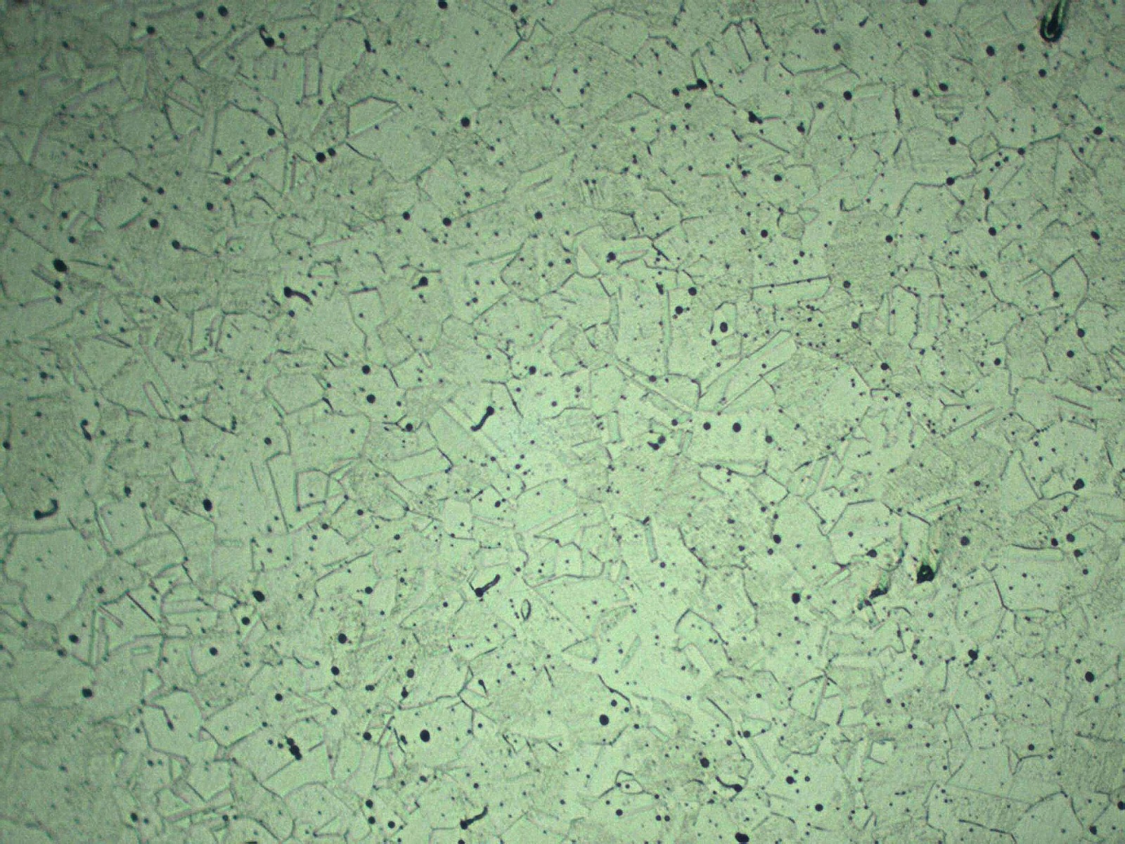

Friday, June 16, 2023

๐Ÿ”ฌ SS 304 Microstructure ๐Ÿ”ฌ

Etchant: Aqua Regia, Magnification: 200X


Title: Exploring the Microstructure of Stainless Steel 304 (SS 304)


Introduction:

Stainless steel 304 (SS 304) is a widely used stainless steel alloy known for its excellent corrosion resistance and versatility. The microstructure of SS 304 plays a crucial role in determining its mechanical properties and overall performance. In this blog, we delve into the microstructural characteristics of SS 304, shedding light on its composition and the resulting implications.


Austenitic Structure:

The microstructure of SS 304 predominantly features an austenitic structure. Austenitic stainless steels possess a face-centered cubic (FCC) crystal structure, rendering them non-magnetic. SS 304 primarily consists of iron (Fe) with approximately 18% chromium (Cr) and 8% nickel (Ni) as the primary alloying elements. This composition contributes to the material's exceptional corrosion resistance.


Homogeneous Grain Structure:

In its annealed condition, SS 304 exhibits a homogeneous microstructure with grains randomly distributed and oriented. These grains form a solid solution of iron, chromium, and nickel atoms, creating a stable and corrosion-resistant matrix. The homogeneous grain structure imparts SS 304 with high ductility, allowing it to be easily formed and fabricated into various shapes.


Effects of Cold Working:

When SS 304 undergoes cold working processes like rolling or bending, its microstructure undergoes deformation. Cold working leads to the formation of dislocations, elongation, and distortion of grains within the material. As a result, the strength and hardness of SS 304 increase while its ductility decreases. This altered microstructure makes cold worked SS 304 suitable for applications requiring enhanced strength, such as structural components in demanding environments.


Minor Alloying Elements:

While chromium and nickel are the primary alloying elements, SS 304 may also contain small amounts of carbon (C), manganese (Mn), and silicon (Si). These elements contribute to the material's overall microstructure but do not significantly alter its fundamental austenitic nature. Carbon, for instance, enhances SS 304's strength and hardness, while manganese aids in reducing the formation of harmful impurities during production processes.


Conclusion:

The microstructure of stainless steel 304, with its austenitic composition and homogeneous grain structure, is instrumental in defining its mechanical properties and corrosion resistance. Understanding the microstructural aspects of SS 304 allows engineers and manufacturers to leverage its excellent corrosion resistance, high ductility, and formability for a wide range of applications. Additionally, the effects of cold working on SS 304's microstructure offer opportunities to tailor its strength and hardness to meet specific requirements. By comprehending the microstructure of SS 304, professionals can make informed decisions when designing and implementing stainless steel components.


๐Ÿค” Want to Read More?๐ŸŽฏ๐Ÿ‘‡
 

https://metallurgicaltest.blogspot.com/2023/06/aisi-316-ss-316-microstructure.html

For Continuous Intersting Details...


Other stainless steel grades that exhibit a similar microstructure to stainless steel 304 (SS 304) are:

1️⃣ Stainless Steel 316 (SS 316): 

SS 316 is an austenitic stainless steel that contains higher amounts of chromium (16-18%) and nickel (10-14%) compared to SS 304. It has a similar FCC crystal structure and provides excellent corrosion resistance, especially in chloride environments. SS 316 shares the same austenitic microstructure as SS 304, making it suitable for various applications such as marine equipment, chemical processing, and medical implants.

2️⃣ Stainless Steel 302 (SS 302): 

SS 302 is another austenitic stainless steel with a similar microstructure to SS 304. It contains a slightly higher carbon content (0.15% maximum) compared to SS 304. This small variation in composition imparts SS 302 with increased strength and hardness, making it suitable for applications that require high mechanical properties, such as springs and fasteners.

3️⃣ Stainless Steel 321 (SS 321): 
SS 321 is an austenitic stainless steel that contains titanium (Ti) as a stabilizing element, which prevents the formation of harmful chromium carbides during high-temperature service. It has a similar microstructure to SS 304 and offers excellent corrosion resistance, particularly in elevated temperature environments. SS 321 is commonly used in applications involving heat exchangers, aircraft exhaust systems, and furnace parts.

4️⃣ Stainless Steel 304L (SS 304L): 
SS 304L is a low-carbon variation of SS 304, where the carbon content is restricted to a maximum of 0.03%. This lower carbon content helps minimize the formation of chromium carbides, which can cause sensitization and intergranular corrosion. SS 304L shares the same microstructure as SS 304 and is often preferred for applications requiring weldability and resistance to sensitization.

It's important to note that while these stainless steel grades have similar microstructures to SS 304, their specific compositions and alloying elements may result in different mechanical properties, corrosion resistance, and application suitability. Therefore, it's essential to consider the unique characteristics of each stainless steel grade when selecting the appropriate material for a specific application.


Wednesday, June 14, 2023

➗ 0.2% Yield Stress ➗


➗ ๐Ÿฌ.๐Ÿฎ% ๐—ฃ๐—ฟ๐—ผ๐—ผ๐—ณ ๐—ฆ๐˜๐—ฟ๐—ฒ๐˜€๐˜€ ➗ 


๐Ÿ”ถ 0.2% proof stress is required instead of normal stress because it is a more accurate measure of a material's strength. Normal stress is the stress that is applied to a material in a direction perpendicular to its cross-section. However, this does not take into account the fact that some materials will deform plastically (permanently) before they reach their normal yield stress. 0.2% proof stress is defined as the stress that will cause a material to deform plastically by 0.2%. This is a more accurate measure of a material's strength because it takes into account the fact that some materials will deform plastically before they reach their normal yield stress.


๐Ÿ‘‰Here are some additional reasons why 0.2% proof stress is preferred over normal stress:


☑️ It is more repeatable and reproducible.

☑️ It is less sensitive to the surface finish of the material.

☑️ It is less sensitive to the presence of defects in the material.

☑️ It is more representative of the actual stress that the material will experience in service.


๐Ÿ”ทFor these reasons, 0.2% proof stress is the preferred method for determining the strength of a material.


๐Ÿ‘‰Here are some examples of how 0.2% proof stress is used:


✔️ In the design of engineering components, such as bridges, buildings, and machinery.

✔️ In the selection of materials for specific applications, such as high-strength steel for use in structural applications.

✔️ In the quality control of manufactured products, such as steel bars and pipes.


๐Ÿ”ฐ 0.2% proof stress is an important property for engineers and designers to understand. It is a measure of a material's strength that is more accurate than normal stress. This makes it a valuable tool for ensuring the safety and reliability of engineering components and products.


๐ŸŽฏ What's Your Thoughts ๐Ÿค”?

https://metallurgicaltest.blogspot.com/2023/06/ductile-and-brittle-fracture-in-tensile.html

๐Ÿ”ฌ Vishal Pambhar ๐Ÿ™๐Ÿ˜Š


#metallurgist #engineering #design #experience #quality #safety #property #engineers #structural #designers #tensile #tensiletest #mechanicaltesting #laboratoryequipment #utm #strengths #testingequipment #labtechnician #labtesting #iso17025 #nabl #qaqcengineer #qualitycontrol #bridgeconstruction #pipeline #failureanalysis #yield #measurement 


Want to know More ๐Ÿ‘‡

https://metallurgicaltest.blogspot.com/2023/06/tensile-test-specimens.html

Absolutely! Let's delve into each point with more details, explaining them in an easy-to-understand manner:


๐Ÿ“Œ Point 1: 0.2% proof stress is used to evaluate the yield strength of materials, particularly metals.


Think of the yield strength as the stress level at which a material starts to change its shape permanently. We use the 0.2% proof stress to measure this critical point in materials, especially metals. It helps us understand how much stress a material can handle before it gets permanently deformed.


๐Ÿ“Œ Point 2: The 0.2% proof stress represents the stress required to cause a 0.2% (or 0.002) permanent deformation in the material.


When we subject a material to stress, it initially stretches or deforms. However, up to a certain point, it can still spring back to its original shape once the stress is removed. The 0.2% proof stress is the stress level at which the material starts to change its shape in a way that it doesn't fully recover. Specifically, it's the stress needed to cause a permanent deformation of 0.2% (or 0.002) in the material.


๐Ÿ“Œ Point 3: The 0.2% proof stress is a reliable reference point for comparing yield strengths of different materials.


To effectively compare the strength of various materials, we need a consistent and reliable measure. The 0.2% proof stress serves as that reference point. By measuring the stress required to cause the same 0.2% permanent deformation, we can accurately compare how different materials behave under load. It ensures fairness and accuracy in evaluating and choosing materials for specific applications.


๐Ÿ“Œ Point 4: The 0.2% proof stress considers the elastic behavior of the material.


Materials have elastic and plastic behaviors. Elastic behavior means that when we apply stress, the material stretches or deforms but can return to its original shape once the stress is removed. The 0.2% proof stress takes into account this elastic behavior, helping us understand the material's ability to withstand loads without permanently deforming.


๐Ÿ“Œ Point 5: The 0.2% proof stress provides information about a material's ability to withstand loads without permanent deformation.


In engineering applications, we often need to ensure that materials can handle certain stresses without getting permanently damaged. By knowing the 0.2% proof stress, we can determine the point at which a material starts to undergo plastic deformation. This information helps us design structures and components that will remain intact under expected loads, without experiencing excessive and permanent changes in shape.


๐Ÿ“Œ Point 6: Normal stress measurements do not provide a clear indication of the yield strength or the material's response to mechanical loads.


Normal stress measurements alone may not give us a complete picture of a material's strength or behavior. They don't specifically account for the transition from elastic to plastic deformation. Therefore, the 0.2% proof stress is preferred as it accurately captures the critical point where permanent deformation begins, offering a clearer understanding of the material's response to mechanical loads.


To summarize, the 0.2% proof stress is a reliable measure used to evaluate the yield strength and behavior of materials. It represents the stress required to cause a 0.2% permanent deformation, allowing for fair comparisons between different materials. By considering the elastic behavior and understanding the material's response to stress, we can make informed decisions in engineering applications to ensure the materials can withstand loads without undergoing permanent deformation.


If needed more to read ๐Ÿ‘‡


Absolutely! Here are some additional details about the 0.2% proof stress, explained in the same easy-to-understand manner:


๐Ÿ“Œ Point 1: The 0.2% proof stress is a measure of a material's ability to withstand stress before permanent deformation occurs.


When we apply stress to a material, such as pulling or stretching it, there's a point at which the material starts to change its shape permanently. This point is known as the yield strength, and the 0.2% proof stress helps us determine exactly where it lies. By measuring the stress required to cause a permanent deformation of 0.2% (or 0.002), we can identify the maximum stress a material can handle before it gets permanently deformed.


๐Ÿ“Œ Point 2: The 0.2% proof stress allows for consistent comparisons between different materials.


In engineering, it's crucial to compare the strength and performance of different materials to select the most suitable one for a particular application. The 0.2% proof stress provides a standardized reference point for these comparisons. By measuring the stress needed to cause a 0.2% permanent deformation, we can fairly assess the yield strengths of various materials and determine which one is better suited for specific engineering needs.


๐Ÿ“Œ Point 3: The 0.2% proof stress considers both the elastic and plastic behavior of the material.


When we subject a material to stress, it exhibits two types of behaviors: elastic and plastic. Initially, in the elastic region, the material deforms under stress but can return to its original shape once the stress is removed. Beyond a certain point, known as the yield point, the material enters the plastic region, where it undergoes permanent deformation. The 0.2% proof stress is a measure that takes into account this transition from elastic to plastic behavior, providing valuable insight into how the material responds to mechanical loads.


๐Ÿ“Œ Point 4: The 0.2% proof stress helps engineers design structures and components that can withstand expected loads.


Understanding a material's ability to handle stress is vital for engineering design. By knowing the 0.2% proof stress, engineers can ensure that structures and components are designed to operate within the material's safe limits. It helps prevent excessive deformation or failure under anticipated loads, ensuring the reliability and longevity of the engineered systems.


๐Ÿ“Œ Point 5: Normal stress measurements alone may not accurately represent a material's yield strength.


Normal stress, which is the force applied perpendicular to a material's surface, is not sufficient on its own to determine the yield strength. Normal stress does not consider the material's behavior beyond the elastic region or its ability to recover its original shape. The 0.2% proof stress, however, provides a more comprehensive understanding of the material's response to stress and its ability to withstand loads without permanent deformation.


To summarize, the 0.2% proof stress is a valuable measure that helps engineers assess the yield strength and behavior of materials. It allows for fair comparisons between different materials, considering their elastic and plastic behavior. By understanding a material's 0.2% proof stress, engineers can design structures and components that can withstand expected loads and ensure the reliability of engineered systems.


๐Ÿ“ฑ Material and Metallurgy Role in Future Technology of Flexible Mobile ๐Ÿ“ฑ


๐Ÿ“ฑMaterial science and metallurgy play crucial roles in the development of flexible mobile technology.๐Ÿ“ฑ

Here are some key aspects:

1️⃣. Flexible Substrates

Flexible mobile devices require substrates that can bend and withstand repeated flexing without compromising functionality. Material scientists are actively exploring flexible materials such as thin films of polymers, graphene, and other flexible electronics materials to serve as the substrate for flexible displays, sensors, and circuitry.

2️⃣. Display Technology: 

Flexible displays are a core component of flexible mobile devices. Researchers are developing flexible OLED (Organic Light-Emitting Diode) and AMOLED (Active Matrix OLED) technologies using flexible substrates and materials. These displays offer the advantage of being lightweight, thin, and resistant to cracking, enabling them to conform to curved surfaces without breaking.

3️⃣. Flexible Circuitry: 

Traditional rigid circuit boards cannot withstand the bending and flexing required in flexible mobile devices. Material and metallurgical advancements are enabling the development of flexible circuits using materials like flexible polymers, stretchable conductive materials, and even nanomaterials. These materials allow circuits to flex, twist, and bend without compromising their electrical properties.

4️⃣. Metamaterials and Nanomaterials: 

Metamaterials and nanomaterials have unique properties that can enhance the performance of flexible mobile devices. Metamaterials are engineered materials with properties not found in nature, such as negative refractive index or tunable electromagnetic responses. They can be used to create compact and efficient antennas or enhance signal processing capabilities in flexible devices. Nanomaterials, on the other hand, offer exceptional mechanical, electrical, and optical properties, enabling the development of flexible components with improved performance and durability.

5️⃣. Mechanical Durability: 

Flexible mobile devices must withstand bending, folding, and twisting motions repeatedly without failure. Material scientists are working on developing durable materials that can endure such mechanical stress. They study the mechanical properties of materials, including their elasticity, fatigue resistance, and fracture toughness, to design materials that can withstand the demanding requirements of flexible devices.

6️⃣. Energy Storage:  

Flexible mobile devices also require advanced energy storage solutions. Material advancements in areas such as flexible batteries and supercapacitors are crucial for powering these devices. Researchers are exploring flexible materials for electrodes and solid-state electrolytes that can enable flexible and lightweight energy storage systems.


➡️ Overall, material science and metallurgy are pivotal in the development of flexible mobile technology. Advancements in these fields are driving the innovation of flexible substrates, displays, circuitry, metamaterials, nanomaterials, and energy storage systems. These developments are instrumental in creating future mobile devices that are more versatile, durable, and conformable to various form factors.


✳️ Here are some points about the role of materials science and metallurgy in the future of flexible mobile devices:

☑️ New materials with improved flexibility, strength, and durability will be needed to create devices that can withstand the rigors of everyday use.

☑️ New manufacturing techniques will be needed to produce these materials in a cost-effective manner.

☑️ Some of the key materials that are being developed for use in flexible mobile devices include organic semiconductors, conductive polymers, and shape memory alloys.

☑️ Some of the techniques that are being developed for manufacturing flexible mobile devices include roll-to-roll manufacturing and 3D printing.

☑️ The development of new materials and manufacturing techniques will be essential for the future of flexible mobile devices.

☑️ These devices offer a number of potential advantages over traditional mobile devices, such as increased durability, portability, and flexibility.

☑️ As these technologies continue to develop, we can expect to see a wide range of new and innovative flexible mobile devices in the years to come.


๐ŸŽฏ Materials science and metallurgy will play a critical role in the future of flexible mobile devices. New materials with improved flexibility, strength, and durability will be needed to create devices that can withstand the rigors of everyday use. In addition, new manufacturing techniques will be needed to produce these materials in a cost-effective manner.

๐Ÿ”ฐSome of the key materials that are being developed for use in flexible mobile devices include:

๐Ÿ”ท* **Organic semiconductors:
These materials are made from carbon-based compounds and offer a number of advantages over traditional inorganic semiconductors, such as flexibility, transparency, and low cost.

๐Ÿ”ท* **Conductive polymers:
These polymers are able to conduct electricity, making them ideal for use in flexible electronic devices.

๐Ÿ”ท* **Shape memory alloys:
These alloys can be deformed and then return to their original shape, making them useful for creating flexible hinges and other components.

In addition to new materials, new manufacturing techniques will also be needed to produce flexible mobile devices. Some of the techniques that are being developed include:

* **Roll-to-roll manufacturing:**
This technique can be used to produce large, flexible sheets of material, which is ideal for use in flexible displays and other components.

* **3D printing:**
This technique can be used to create complex, three-dimensional objects, which is ideal for creating flexible electronic devices with complex shapes.

The development of new materials and manufacturing techniques will be essential for the future of flexible mobile devices. These devices offer a number of potential advantages over traditional mobile devices, such as increased durability, portability, and flexibility. As these technologies continue to develop, we can expect to see a wide range of new and innovative flexible mobile devices in the years to come.


Here are some specific examples of how materials science and metallurgy are being used to develop flexible mobile devices:

๐Ÿ“ฑLG Electronics has developed a flexible OLED display that is made from organic semiconductors.
** This display is thinner and lighter than traditional LCD displays, and it is also more durable.

๐Ÿ“ฑSamsung has developed a flexible smartphone that is made from a material called graphene.
** Graphene is a very strong and lightweight material that is also transparent.

๐Ÿ“ฑIntel has developed a flexible computer chip that is made from a material called gallium arsenide.
** Gallium arsenide is a semiconductor material that is known for its high performance.

๐Ÿ’กThese are just a few examples of the many ways that materials science and metallurgy are being used to develop flexible mobile devices. As these technologies continue to develop, we can expect to see even more innovative and exciting flexible mobile devices in the years to come.


Tuesday, June 13, 2023

๐Ÿ”ฌ Exploded Graphite ๐Ÿ”ฌ

๐Ÿ”ฌ Exploded Graphite ๐Ÿ”ฌ


๐Ÿ”น Exploded Graphite in Ductile Iron:
   - Ductile iron: type of cast iron with graphite nodules.
   - Exploded graphite: fragmented or dispersed graphite in ductile iron.

๐Ÿ”น Formation of Exploded Graphite:
   - Causes: excessive inoculation, rapid cooling, improper pouring temperatures.
   - Factors: excessive nodulizing agents (e.g., ferrosilicon, magnesium).
   - Consequences: fragmented graphite within the iron structure.

๐Ÿ”น Effects of Exploded Graphite:
   - Weakening: stress concentration, reduced ductility.
   - Performance impact: decreased load and impact resistance.
   - Issues: premature failure, lower tensile strength, reduced fatigue life, increased brittleness.

๐Ÿ”น Prevention of Exploded Graphite:
   - Casting process control: crucial for prevention.
   - Nodulizing agent selection: careful choice and controlled addition.
   - Pouring temperature: maintain appropriate levels.
   - Cooling rates: control to avoid fragmented graphite formation.
   - Inoculation process: monitor dosage and timing to prevent excess inoculation.


Title: Exploded Graphite in Ductile Iron: Understanding its Formation, Effects, and Prevention

Introduction:
Ductile iron, also known as nodular or spheroidal graphite iron, is a versatile material widely used in various industries. It possesses excellent mechanical properties due to the presence of graphite nodules within its microstructure. However, in certain instances, a phenomenon known as exploded graphite can occur, which can have detrimental effects on the material's properties. In this post, we will explore the formation, effects, and preventive measures of exploded graphite in ductile iron.

Formation Mechanisms:
Exploded graphite is formed as a result of specific factors during the casting process. Excessive inoculation, where nodulizing agents such as ferrosilicon or magnesium are overdosed, can lead to fragmented graphite. Rapid cooling rates during solidification, improper pouring temperatures, or inadequate control of the inoculation process can also contribute to the formation of exploded graphite.

Effects on Mechanical Properties:
The presence of exploded graphite can significantly impact the mechanical properties of ductile iron. It weakens the material's structure by creating stress concentrations, reducing ductility, and decreasing its ability to withstand load and impact. Components with exploded graphite are more susceptible to premature failure, have lower tensile strength, reduced fatigue life, and increased brittleness.

Preventive Measures:
To prevent the formation of exploded graphite, strict control and optimization of the casting process are essential. Careful selection and controlled addition of nodulizing agents ensure the formation of desirable graphite structures. Maintaining appropriate pouring temperatures and controlling cooling rates help avoid the formation of fragmented graphite. Regular monitoring of the inoculation process, including dosage and timing, is crucial to prevent excessive inoculation that can lead to exploded graphite.

Additional Considerations:
In addition to prevention measures, non-destructive testing methods such as ultrasonic testing and X-ray radiography can be employed to detect the presence of exploded graphite in ductile iron components. Heat treatment processes, such as annealing or stress relieving, can also help mitigate the detrimental effects of exploded graphite by promoting carbon redistribution and restoring the desired nodular graphite structure.

Conclusion:
Exploded graphite in ductile iron poses challenges to the material's mechanical properties and performance. By understanding its formation mechanisms, effects, and implementing preventive measures, manufacturers can ensure the production of high-quality ductile iron components. Ongoing research and advancements in casting techniques contribute to the continuous improvement of preventing and mitigating the occurrence of exploded graphite.


The microstructure of exploded graphite in ductile iron is an important aspect to consider in understanding its formation and effects. Here is the best information on the microstructure of exploded graphite:

1. Fragmented Graphite Morphology:
   - Exploded graphite appears as fragmented or elongated graphite particles within the microstructure of ductile iron.
   - The graphite particles exhibit irregular shapes and are often separated from the surrounding matrix.
   - The fragmentation occurs due to the presence of stress concentration points caused by factors such as excessive inoculation or rapid cooling.

2. Distribution and Density:
   - The extent and distribution of exploded graphite within the microstructure can vary depending on the casting conditions and the specific alloy composition.
   - It can be localized in certain areas or spread throughout the material, depending on the severity of the graphite fragmentation.
   - The density of exploded graphite can vary as well, with higher concentrations leading to a higher density of fragmented graphite particles.

3. Effects on Mechanical Properties:
   - The presence of exploded graphite within the microstructure weakens the overall mechanical properties of ductile iron.
   - Fragmented graphite acts as stress concentration points, reducing the material's resistance to load and impact.
   - It diminishes the ductility and toughness of the material, making it more prone to brittle fracture.
   - The density and distribution of fragmented graphite can further influence the severity of these effects.

4. Microstructural Analysis Techniques:
   - Microstructural analysis techniques such as optical microscopy and scanning electron microscopy (SEM) are commonly employed to examine the microstructure of exploded graphite in ductile iron.
   - These techniques allow for detailed observation and characterization of the fragmented graphite morphology, distribution, and its relationship with the surrounding matrix.

5. Heat Treatment and Graphite Restoration:
   - Heat treatment processes, such as annealing or stress relieving, can help mitigate the effects of exploded graphite on the microstructure.
   - Controlled heat treatments promote the redistribution of carbon, allowing for the restoration of the desired nodular graphite structure.
   - The effectiveness of heat treatment in restoring the microstructure depends on the severity of the exploded graphite and the specific heat treatment parameters applied.

Understanding the microstructure of exploded graphite in ductile iron is crucial for assessing its impact on mechanical properties and developing effective prevention and mitigation strategies. Microstructural analysis techniques and appropriate heat treatment processes play a significant role in evaluating and restoring the graphite morphology within the microstructure.

Monday, June 12, 2023

♦️ Mastering Welding Quality ♦️

Title: "Mastering Welding Quality: Overcoming Challenges for Flawless Welds"


Introduction:

Welding is a crucial process in various industries, providing strength and durability to structures and components. However, poor welding quality can lead to compromised integrity, safety concerns, and costly rework. In this blog, we will explore common challenges faced in welding and provide practical tips and solutions to achieve superior welding quality.


1. Understanding the Common Causes of Poor Welding Quality:

   - Inadequate Welder Training: Lack of proper training and experience can result in inconsistent welds, insufficient penetration, and improper technique.

   - Improper Welding Parameters: Failure to optimize welding parameters such as heat input, travel speed, and electrode selection can lead to defects like porosity, undercutting, or lack of fusion.

   - Inadequate Joint Preparation: Poorly prepared joints with inadequate beveling, incorrect fit-up, or inadequate cleaning can compromise the quality of the weld.


2. Effective Strategies for Improving Welding Quality:

   - Comprehensive Welding Procedure Specification (WPS): Developing a detailed WPS ensures standardized procedures, including pre-welding inspections, welding techniques, and quality control measures.

   - Adequate Pre-Welding Preparation: Emphasize the importance of proper joint preparation, ensuring clean surfaces, correct fit-up, and appropriate bevel angles to promote sound welds.

   - Welder Qualification and Training Programs: Invest in training programs to enhance welders' skills, ensuring they understand welding fundamentals, proper technique, and the importance of quality control.

   - Rigorous Inspection and Quality Assurance: Implement robust inspection processes, including visual inspection, non-destructive testing methods, and quality control checkpoints throughout the welding process.


3. Troubleshooting Common Welding Defects:

   - Porosity: Discuss causes such as moisture, inadequate shielding gas, or improper electrode storage, and provide solutions such as proper material handling, adequate gas coverage, and electrode storage techniques.

   - Lack of Fusion: Address the root causes, such as improper welding technique or insufficient heat input, and provide guidance on proper joint preparation, electrode selection, and technique adjustment.

   - Cracking: Explain the various types of cracking (hot cracking, cold cracking) and their causes, highlighting measures like preheating, controlling cooling rates, and selecting appropriate filler materials.


4. Welding Quality Control Techniques:

   - Non-Destructive Testing (NDT): Introduce common NDT methods like visual inspection, ultrasonic testing, radiography, and explain their benefits in detecting hidden defects and ensuring welding quality.

   - Welding Procedure Qualification Testing (WPQT): Describe the importance of WPQT to validate welding procedures, ensuring they meet industry standards and specifications.

   - Documentation and Traceability: Highlight the significance of proper documentation, including WPS, welder qualifications, inspection reports, and material certifications for traceability and quality control.


5. Continuous Improvement and Training Programs:

   - Emphasize the importance of ongoing training and professional development to stay updated with the latest welding techniques, equipment advancements, and industry best practices.

   - Encourage welders and supervisors to actively participate in forums, workshops, and industry events to share knowledge and experiences.


Conclusion:

Achieving high-quality welds requires a combination of proper training, adherence to welding procedures, effective quality control, and continuous improvement. By addressing common challenges and implementing robust strategies, welders and organizations can overcome poor welding quality, ensuring safe and reliable welds that meet the highest industry standards. Remember, investing in welding quality is an investment in the long-term integrity and success of your projects.


๐Ÿ”ป.  


Here are some short points regarding poor welding quality:


1. Inadequate training leads to inconsistent and poor-quality welds.

2. Incorrect welding parameters result in defects like porosity and lack of fusion.

3. Poor joint preparation compromises the quality of the weld.

4. Insufficient shielding gas coverage can lead to weld contamination.

5. Improper electrode storage causes issues like moisture absorption and porosity.

6. Lack of preheating can result in cracking and reduced weld strength.

7. Inadequate welder qualification leads to substandard welds.

8. Insufficient cleaning of surfaces before welding can cause contamination and defects.

9. Welding on dirty or rusty materials affects weld quality.

10. Inconsistent heat input results in variations in weld quality.

11. Failure to control cooling rates can lead to cracking and distortion.

12. Welding without proper ventilation can cause weld defects due to fume exposure.

13. Poor electrode selection can result in insufficient penetration or excessive spatter.

14. Lack of inspection during welding allows defects to go unnoticed.

15. Inadequate filler metal selection leads to weak or brittle welds.

16. Using worn-out or damaged welding equipment compromises weld quality.

17. Ignoring the importance of proper weld sequencing causes distortion and stress concentration.

18. Improper electrode angle affects weld penetration and bead appearance.

19. Failure to remove surface contaminants like oil, grease, or paint leads to poor adhesion.

20. Welding without proper joint fit-up can result in misalignment and lack of fusion.

21. Insufficient gas flow or improper gas mixture affects shielding and leads to defects.

22. Inadequate control of welding speed affects weld bead shape and penetration.

23. Poor welder technique, such as excessive weaving, can cause inconsistencies.

24. Welding without proper grounding can result in electrical and safety issues.

25. Failure to follow proper weld sequencing leads to incomplete fusion.

26. Insufficient post-weld cleaning can result in contamination and reduced corrosion resistance.

27. Welding without proper electrode manipulation causes irregular bead shape and poor fusion.

28. Lack of knowledge about proper pre- and post-weld heat treatment affects weld strength.

29. Ignoring the importance of weld parameter adjustments for different joint configurations results in poor-quality welds.

30. Neglecting quality control measures during welding leads to substandard and unsafe welds.


These points highlight various factors and issues that contribute to poor welding quality.

Sunday, June 11, 2023

๐Ÿ”ฌ Micro Decarburization Overview ๐Ÿ”ฌ

Magnification: 100x, Above Material is SAE-52100, Etchant: 2% Nital


Decarburization refers to the process of carbon loss from the surface layer of a material, usually due to exposure to high temperatures and oxidizing environments. It commonly occurs in carbon-rich alloys, such as steels, where carbon plays a significant role in determining the material's properties and performance. Decarburization can have various effects on the material, including changes in hardness, strength, wear resistance, and dimensional stability.

During decarburization, the carbon atoms near the material's surface react with the surrounding atmosphere, typically containing oxygen, water vapor, or carbon dioxide. This reaction results in the formation of carbon monoxide or carbon dioxide gas, leading to the removal of carbon from the surface layer. The depth of decarburization can vary depending on factors such as temperature, time, alloy composition, and the nature of the surrounding atmosphere.

The loss of carbon near the material's surface can significantly impact its mechanical, physical, and chemical properties. Carbon is a crucial element in strengthening alloys, forming hard carbides, and enhancing wear resistance. Therefore, decarburization can result in reduced hardness, strength, and wear resistance of the material. It can also affect other properties, such as fatigue resistance, corrosion resistance, surface finish, dimensional stability, electrical conductivity, and magnetic properties.

Decarburization is of great importance in various industries, including metallurgy, manufacturing, and heat treatment. It is a phenomenon that needs to be carefully controlled and managed to ensure the desired properties and performance of carbon-rich materials. Preventive measures, such as the use of protective atmospheres, surface coatings, controlled cooling rates, and material selection, are employed to minimize or prevent decarburization in critical applications.

Understanding the mechanisms and effects of decarburization is crucial for material scientists, engineers, and manufacturers to optimize processes, develop suitable alloys, and ensure the quality and reliability of the final products. Through proper control and prevention of decarburization, the desired material properties can be maintained, allowing for optimal performance in various applications.

Factors Affecting Decarburization:


1. Temperature: Decarburization is temperature-dependent, with higher temperatures accelerating the rate of carbon loss. Elevated temperatures promote the diffusion of carbon atoms from the material's surface, leading to increased decarburization depth.


2. Time: The duration of exposure to high temperatures directly affects decarburization. Prolonged exposure allows for more significant carbon loss and deeper decarburization.


3. Atmosphere: The composition of the surrounding atmosphere plays a vital role in decarburization. Oxidizing atmospheres, such as those containing oxygen, water vapor, or carbon dioxide, enhance decarburization by facilitating the oxidation of carbon.


4. Alloy Composition: The chemical composition of the material influences its susceptibility to decarburization. Alloys with higher carbon content are more prone to decarburization compared to low-carbon alloys.


5. Surface Condition: The condition of the material's surface can affect decarburization. Rough surfaces provide more active sites for oxidation reactions, potentially increasing the rate and depth of decarburization.


Prevention of Decarburization:


1. Protective Atmospheres: Implementing controlled atmospheres during heat treatment processes is an effective way to prevent decarburization. Inert gas atmospheres, such as nitrogen or argon, or reducing atmospheres, such as hydrogen or dissociated ammonia, can be used to shield the material from oxidizing environments.


2. Surface Coatings: Applying protective coatings, such as paints, ceramics, or metal layers, can create a barrier between the material and the surrounding atmosphere. These coatings act as a shield, preventing carbon loss and reducing the depth of decarburization.


3. Vacuum Heat Treatment: Performing heat treatment processes under vacuum conditions eliminates the presence of reactive gases, effectively preventing decarburization. Vacuum heat treatment is commonly employed for materials sensitive to oxidation, such as tool steels.


4. Controlled Cooling Rates: Proper control of the cooling rate after heat treatment can minimize the depth of decarburization. Rapid cooling methods, such as quenching in oil or water, can reduce the time available for carbon diffusion and limit the extent of decarburization.


5. Material Selection: Choosing alloys with lower carbon content or alloying elements that promote resistance to decarburization can help mitigate the effects of carbon loss. For example, using stainless steels or heat-resistant alloys with high chromium content can improve resistance to decarburization.


By considering these factors and implementing appropriate prevention measures, decarburization can be effectively controlled, ensuring the desired material properties and performance in various applications.


Title: Micro Decarburization Depth Measurement: Techniques and Significance


Introduction:

Micro decarburization is a critical phenomenon that affects the integrity and performance of materials, particularly in high-temperature applications. The accurate measurement of decarburization depth is essential for understanding the extent of carbon loss near the surface and evaluating the material's suitability for specific applications. This post explores various techniques used for micro decarburization depth measurement and discusses their significance in material characterization and quality control.


1. Metallographic Examination:

Metallographic analysis is a widely used technique for assessing decarburization depth. It involves preparing cross-sectional samples, grinding, polishing, and etching to reveal the microstructure. The decarburized layer appears lighter due to the absence of carbon, allowing for depth measurement under a microscope. Metallography provides valuable information on the depth profile and the nature of decarburization.


2. Microhardness Testing:

Microhardness testing can also provide insights into the decarburization depth. By performing a series of microhardness indentations across the decarburized region, it is possible to observe variations in hardness as carbon content decreases. The hardness gradient correlates with the depth of decarburization, allowing for quantitative measurements.


3. Scanning Electron Microscopy (SEM):

SEM is a powerful tool for examining surface morphology and characterizing decarburization depth. By using backscattered electron imaging or energy-dispersive X-ray spectroscopy (EDS), SEM can visualize and analyze the elemental composition and carbon distribution near the surface. This technique provides valuable qualitative and semi-quantitative information about decarburization depth.


4. Electron Probe Microanalysis (EPMA):

EPMA is a high-resolution technique that allows for the precise measurement of decarburization depth. By utilizing an electron beam to scan the sample's surface, EPMA can map the carbon content and identify the transition zone between the decarburized layer and the unaffected material. EPMA provides accurate and quantitative measurements of decarburization depth.


5. X-ray Diffraction (XRD):

XRD is employed to determine the phase composition and identify changes in crystal structure due to decarburization. By analyzing the diffraction patterns, XRD can provide information about the depth and extent of decarburization. This technique is particularly useful for measuring the decarburization depth in heat-treated steels.


Significance of Micro Decarburization Depth Measurement:

Accurate measurement of decarburization depth has several practical implications:


- Quality Control: By quantifying the decarburization depth, manufacturers can ensure that material meets the required specifications and standards.


- Material Performance: Decarburization depth directly influences material properties such as hardness, strength, and fatigue resistance. Measurement helps assess the impact of decarburization on material performance.


- Failure Analysis: In cases of component failure, measuring the decarburization depth can provide insights into the root cause, enabling corrective actions and preventing future failures.


- Process Optimization: Depth measurement allows manufacturers to optimize heat treatment processes, atmosphere control, and surface protection methods to minimize decarburization.


Conclusion:

Accurate measurement of micro decarburization depth is crucial for understanding material behavior, ensuring quality control, and optimizing processes in various industries. The combination of metallography, microhardness testing, SEM, EPMA, and XRD provides valuable insights into the depth and extent of decarburization, enabling informed decision-making and enhancing material performance.


By employing these measurement techniques, researchers, engineers, and material scientists can gain a comprehensive understanding of micro decarburization and its impact on materials used in high-temperature applications.


 Here are some key properties that can be affected by decarburization:

1. Hardness: Decarburization results in the loss of carbon from the surface layer, which can significantly impact the material's hardness. The reduced carbon content leads to a softer surface, compromising the material's overall hardness and wear resistance.

2. Strength: Carbon plays a crucial role in strengthening alloys, and decarburization diminishes the carbon concentration near the surface. As a result, the strength of the material can be reduced, leading to decreased load-bearing capacity and structural integrity.

3. Wear Resistance: Carbon contributes to the formation of hard carbides in alloys, which enhance wear resistance. Decarburization reduces the carbon content, depleting the formation of these carbides and diminishing the material's wear resistance properties.

4. Fatigue Resistance: Fatigue resistance is a critical property for materials subjected to cyclic loading. Decarburization can negatively impact fatigue life by reducing the material's strength and altering its microstructure, leading to crack initiation and propagation.

5. Corrosion Resistance: Carbon, particularly in stainless steels, provides corrosion resistance by forming a protective oxide layer on the material's surface. Decarburization reduces the carbon content, thereby compromising the material's ability to form and maintain this protective layer, leading to increased susceptibility to corrosion.

6. Surface Finish: Decarburization often results in surface roughness and irregularities due to the loss of carbon and altered microstructure. This can adversely affect the material's appearance, surface quality, and dimensional accuracy, which are crucial in many applications.

7. Dimensional Stability: Decarburization can cause dimensional changes in materials due to the volume reduction resulting from carbon loss. This can lead to distortion, warping, or dimensional instability, which can be problematic in applications where precise dimensions are required.

8. Electrical Conductivity: Carbon is a conductor of electricity, and its reduction through decarburization can result in decreased electrical conductivity in materials. This can be significant in applications where electrical conductivity is a critical property, such as electrical contacts or conductive components.

9. Magnetic Properties: In some alloys, carbon influences the magnetic properties, such as magnetic permeability or coercivity. Decarburization can alter these magnetic properties, affecting the material's response to magnetic fields and its suitability for magnetic applications.

It is important to note that the extent to which these properties are affected by decarburization depends on factors such as the depth of decarburization, the specific alloy composition, and the intended application of the material. Therefore, controlling and minimizing decarburization is crucial to preserving the desired properties of carbon-rich alloys.

Types of Metal Testing

 There are several types of metal testing used to evaluate the properties and quality of metals. Here are some common types of metal testing...